If I understand correctly, these are 4x SC220 enclosures for the SC8000 SAN. Although there is no IO interruption to the SAN, ideally this should be done during scheduled outage. Ensure that backup on current CML LUNs have been taken prior to this activity. The steps below need to be precisely followed to avoid outage and issues.
Required materials:
- 4x SC220 enclosures with its spindles.
- 4x additional minimum length of 2m mini-SAS HD to SAS cables.
- 6x minimum length of 0.5m SAS to SAS cables.
- 2x 4-port low-profile LSI SAS9206-16E SAS HBA.
- 2x full-height 2-port iSCSI PCI bracket.
- Velcro and label machine.
Here’s the plan and tasks:
- Verify current SAS cabling
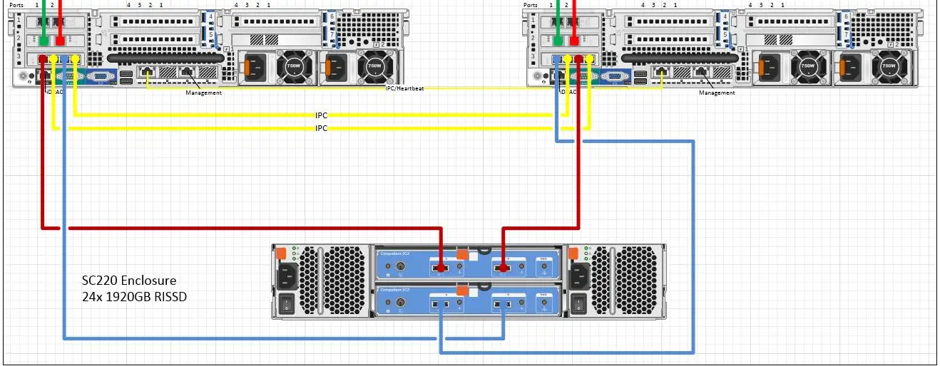
Ensure that current SAS cabling is according to figure 1 below.
- Install 2x additional SAS cards and re-arrange PCI cards on both SC8000 controllers in rolling fashion.
The 2x SAS cards and 2x full-height PCI brackets come with the SC8000 systems. Note that this will cause a split-second front-end IO disruption when the LUNs failover to the other controller. Monitoring system will generate alerts and there will be a call from Dell Pro Support. It is transparent to servers. Current CML SAN layout is attached
Sequence:
- Shut SC8000 A down, all LUNs are served by SC8000 B.
- Install and re-arrange PCI cards on SC8000 A.
- Power SC8000 A back on, inventory and health check, do not re-balance.
- If health check on SC8000 A passed, shutdown SC8000 B.
- Install and re-arrange PCI cards on SC8000 B.
- Inventory and health check on SC8000 B. Re-balance if health check passed.
After new SAS card installation and PCI cards re-arrangement, the cards layout should be:
- Slot 1: 2-port low-profile QLogic QLE2662 16G FC HBA
- Slot 2: 4-port low-profile LSI SAS9206-16E 6Gbps SAS HBA.
- Slot 3: 4-port low-profile LSI SAS9206-16E 6Gbps SAS HBA.
- Slot 4: 2-port full-height 1GbE QLogic QLE4062 iSCSI HBA.
Reference:
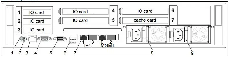
Figure 2: SC8000 rear port layout.
- Adding enclosures
Adding three enclosures are going to be done in two phases:
- Modify current setup from one SC220 enclosure single chain to two SC220 enclosures single chain.
Single chain two enclosures side A
- Ensure that the new second SC220 enclosure is powered off and mounted securely to the rack immediately next to the current SC220 labelled as ENCLOSURE 1 with nothing connected to it except power cords.
- Disconnect Chain 1: Side A cables (maroon lines) on both endpoints. Turn on the second SC220 enclosure. Wait until it finished booting up. The front status LED should be fully lit green and lit blue. Note that this cause a brief unnoticeable back-end IO disruption.
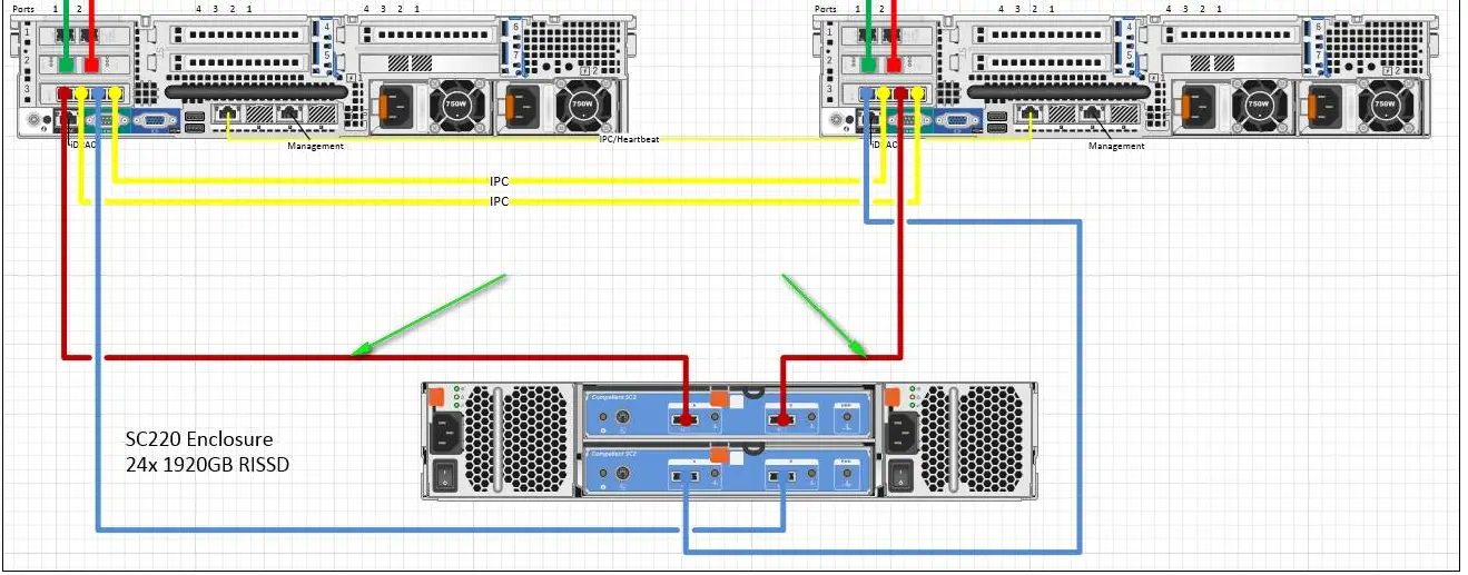
Figure 3: Removal of Chain 1: Side A SAS connections from current topology.
- Connect enclosure 1 top EMM port B to enclosure 2 top EMM port A.
- ConnectSC8000 A slot 2 port 1 to enclosure 1 top EMM port A.
- Connect SC8000 B slot 2 port 3 to enclosure 2 top EMM port B.
- Label enclosure as ENCLOSURE 2.
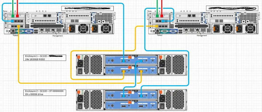
- Verify the new Chain 1: Side A connectivity (contact Hendrik). You will end up with this:
Figure 4: Chain 1: Side A new topology.
Single chain two enclosures side B
- Disconnect Chain 1: Side B SAS connections indicates as orange lines in figure 4. Note that this cause a brief unnoticeable back-end IO disruption.
- Connect enclosure 1 bottom EMM port B to enclosure 2 bottom EMM port A.
- Connect SC8000 A slot 3 port 3 to enclosure 2 bottom EMM port B.
- Connect SC8000 B slot 3 port 1 to enclosure 1 bottom EMM port A.
- Verify the new Chain 1: Side B connectivity (contact Hendrik). You will end up with this:
Figure 5: Chain 1: Side B new topology.
- Adding new chain with two new SC220 enclosures.
- Ensure that enclosure 3 is located immediate to enclosure 2.
- Ensure that enclosure 4 is located immediate to enclosure 3.
- Ensure that enclosure 5 is located immediate to enclosure 4.
- Ensure that both enclosure 3, 4 and 5 are turned off. Label as ENCLOSURE 3, ENCLOSURE 4 and ENCLOSURE 5.
- Connect enclosure 3 top EMM port B to enclosure 4 top EMM port A.
- Connect enclosure 4 top EMM port B to enclosure 5 top EMM port A.
- Connect enclosure 3 bottom EMM port B to enclosure 4 bottom EMM port A.
- Connect enclosure 4 bottom EMM port B to enclosure 5 bottom EMM port A.
- Turn enclosure 3, 4 and 5 on and wait until it is finished to boot up. The front green and blue light must be fully lit.
- Connect SC8000 A slot 2 port 3 to enclosure 3 top EMM port A.
- Connect SC8000 A slot 3 port 1 to enclosure 5 bottom EMM port B.
- Connect SC8000 B slot 2 port 1 to enclosure 5 top EMM port B.
- Connect SC8000 B slot 3 port 3 to enclosure 3 bottom EMM port A.
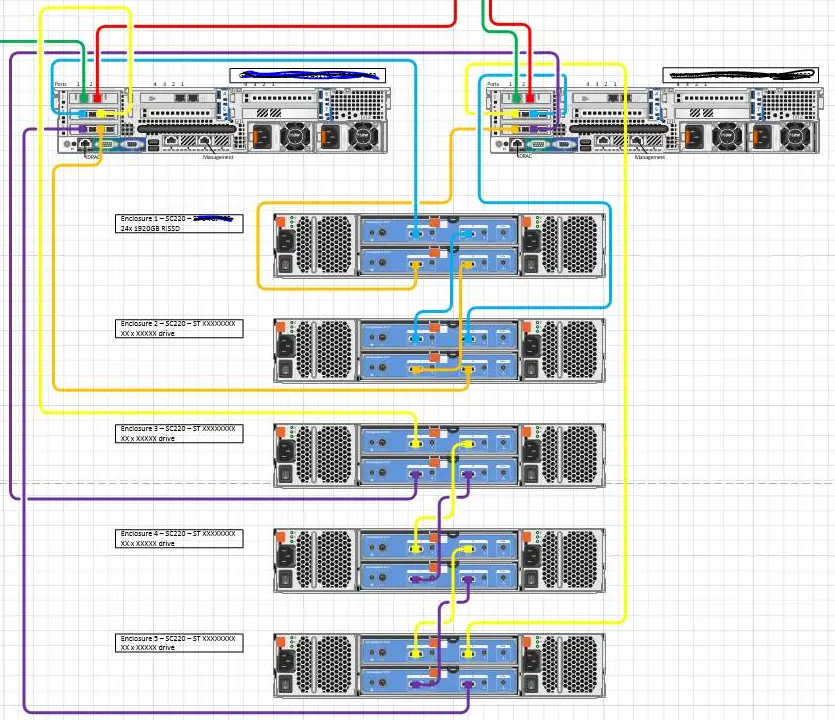
- You’ll end up with this. I’ll verify remotely once it is done..
- Once the verification is completed, remove the IPC connections: the LAN cable that goes from IPC LAN port on both controllers and the SAS cables that are connected to slot 3 port 2 and 4 on both controllers.
Figure 6: 2 controllers, 2 chains, 2 sides, 5 enclosures topology
You will be taking out and in excess of after completion:
- 2x mini-SAS HD to mini-SAS HD cables from the SAS IPC connections.
